Saturday, December 6, 2008
Mikrotik VPN: Point ot Point Tunnel Protocol (PPTP)
General application of PPTP tunnels:
* For a secure router to router tunnels over the internet
* To link (bridge) local LANs or Intranets (EoIP think is also used)
* For mobile or remote clients to remotely access an intranet / LAN of a company (see PPTP setup for Windows for more information)
PPTP connction is each composed of a server and a client. The Mikrotik RouterOS may funcion as a server or the client - or, the various configurations, it may be some connections for the server and client for other connections. For example, the client created below could connect to a windows 2000 server, another Mikrotik Router, or another router which supports a PPTP server.
Description
PPTP is a secure tunnels for transporting IP traffic using PPP. PPTP encapsulates PPP in virtual lines that run over IP. PPTP incorporates PPP and the MPPE (Microsoft Point to Point Encryption) to make Encrypted links. The purpose of this protocol si to make well-managed secure connection (clients are avialable for and / or included in almost all OSS including Windows).
PPTP incluldes PPP authentication and accounting for each PPTP connection. Full authentication and accouting for each connection may be done through a radius of the client or Locally.
MPPE 40bit RC4 and MPPE 128bit RC4 encryption are supported.
PPTP traffic uses TCP port 1723 and IP protocol GRE (Generic Routing Encapsulation, the IP protocol ID 47), as Assigned by the internet Assigned Number Authority (IANA). PPTP can be used with most firewalls and routers by enabling traffic destined for TCP port 1723 and the protocol 47 traffic to be routerd through the firewall or router.
PPTP connection my be limited or dr to set up a masqueraded Policia /NAT IP connction. Please see the Micorsoft and RFC linke at the end of the section for more information.
PPTP Client Setup
Submenu Level: /interace pptp-client
Property Description
name (name; default: pptp-out1) - interface name for reference
mtu (interger; default: 1460) - Maximum transmits Unit. the optimal value is the MTU of the interface the tunnel is working over decreased by 40 (so, for 1500-byte ethernet link, set the MTU to 1460 to avoid fragmentaion of packets)
mrt (integer; default:1460) - Maximum Receive Unit. The optimal vlaue is the MTU of the interface the tunnel is working over decreased by 40 (so, for 1500-byte ethernet link, set the MRU to 1460 to aviod fragmentation of packets)
connect-to (IP address) - the IP address of the PPTP server to connect to
user (string) - user name to use when logging on the remote server
password (string; default: "") - user password to use when loggin to the remote server
profile (name: default: default) - profile to use when connecting to the remote server
add-default-router (yes I no; default: no) - whether to use the server which this client is connected to as its default router (gateway)
Example
to set up PPTP client named test2 using username john with password john to connection the 10.1.1.12 PPTP server and use it as the default gateway:
[admin@Mikrotik] interface pptp-client> add name=test2 connect-to=10.1.1.12 \
\.. user=john add-default-route=yes passowrd=john
[admin@Mikrotik] interface pptp-client>print
Flage: X - disabled, R - running
0 X name="test2" mtu=1460 mru=1460 connect-to=10.1.1.12 user="john"
password="john" profile=default add-default-route=yes
[admin@Mikrotik] interface pptp-client> enable 0
Monitoring PPTP Client
Command name: /interface pptp-clent monitor
Property Description
Statistics:
Uptime (time) connection time displayed in days, hours, minutes, and seconds
encoding (string) - encrytion and encording (if asymmetric, separated with "/") being userd in this connection
status (string) - staturs of the client:
#Dialing - attempting to make a connection
#Verifying passowrd... - connection has been established tothe server, passwrod verification in progress
#connected - self-explanatory
#Terminated - interface is not enabled or the other side will not establish a connection
Example
Example of an established connection:
[admin@Mikrotik] interface pptp-client> monitor test2 uptime: 4h35s
encoding: MPPE 128 bit, stateless
status: connected
[admin@Mikrotik] interface pptp-client>
PPTP server setup
Submenu level : /interface pptp-server server
[admin@Mikrotik] interface pptp-server server> print
enabled: no
mtu: 1460
mru: 1460
authenticaion: mschap2
default-profile: default
[admin@Mikrotik] interface pptp-server server>
Description
The PPTP server supports unlimited connections form clients. For each cureent connection, a dynamic interface is created.
Property Description
enabled (yes I no; default:no) - defines whether PPTP server is enabled or not
mtu (integer; default: 1460 ) - Maximum Transmit Unit. The optimal vlaue is the MTU of the interface the tunnel is working over decreased by 40 (so, for 1500- byte ether net link,set the MTU to 1460 to avoid fragmentation of packets)
mru (integer; default: 1460) - Maximum Receive Unit. The optimal value is the MTU of the interface the tunnel is working over decreased by 40 (so, for 1500-byte ethernet link, set the MTU to 1460 to avoid fragmentation of packets)
authentication (multiple choice: pap chap mschap1 mschap2; default: mschap2) - authentication algorithm
default-profile (name; default: default) - default profile to use
Example
To enable PPTP server:
[admin@MikroTik] interface pptp-server server> set enabled=yes
[admin@MikroTik] interface pptp-server server> print
enabled: yes
mtu: 1460
mru: 1460
authentication: mschap2
default-profile: default
[admin@MikroTik] interface pptp-server server>
PPTP Server Users
Submenu level : /interface pptp-server
Description
There are two types of items in PPTP server configuration - static users and dynamic connections. A dynamic connection can be established if the user database or the default-profile has its local-address and remote-address set correctly. When static users are added, the default profile may be left with its default values and only P2P user (in /ppp secret) should be configured. Note that in both cases P2P users must be configured properly.
Property Description
name - interface name
user - the name of the user that is configured statically or added
dynamically
Statistics:
mtu - shows (cannot be set here) client's MTU
client-address - shows (cannot be set here) the IP of the connected client
uptime - shows how long the client is connected
encoding (string) - encryption and encoding (if asymmetric, separated with '/') being used in this connection
Example
To add a static entry for ex1 user:
[admin@MikroTik] interface pptp-server> add user=ex1
[admin@MikroTik] interface pptp-server> print
Flags: X - disabled, D - dynamic, R - running
# NAME USER MTU CLIENT-ADDRESS UPTIME ENC...
0 DR ex 1460 10.0.0.202 6m32s none
1 pptp-in1 ex1
[admin@MikroTik] interface pptp-server>
In this example an already connected user ex is shown besides the one we just added.
PPTP Router-to-Router Secure Tunnel Example
The following is an example of connecting two Intranets using an encrypted PPTP tunnel over the Internet.
There are two routers in this example:
* [HomeOffice]
Interface LocalHomeOffice 10.150.2.254/24
Interface ToInternet 192.168.80.1/24
* [RemoteOffice]
Interface ToInternet 192.168.81.1/24
Interface LocalRemoteOffice 10.150.1.254/24
Each router is connected to a different ISP. One router can access another router through the Internet.
On the PPTP server a user must be set up for the client:
[admin@HomeOffice] ppp secret> add name=ex service=pptp password=lkjrht
local-address=10.0.103.1 remote-address=10.0.103.2
[admin@HomeOffice] ppp secret> print detail
Flags: X - disabled
0 name="ex" service=pptp caller-id="" password="lkjrht" profile=default
local-address=10.0.103.1 remote-address=10.0.103.2 routes==""
[admin@HomeOffice] ppp secret>
Then the user should be added in the PPTP server list:
[admin@HomeOffice] interface pptp-server> add user=ex
[admin@HomeOffice] interface pptp-server> print
Flags: X - disabled, D - dynamic, R - running
# NAME USER MTU CLIENT-ADDRESS UPTIME ENC...
0 pptp-in1 ex
[admin@HomeOffice] interface pptp-server>
And finally, the server must be enabled:
[admin@HomeOffice] interface pptp-server server> set enabled=yes
[admin@HomeOffice] interface pptp-server server> print
enabled: yes
mtu: 1460
mru: 1460
authentication: mschap2
default-profile: default
[admin@HomeOffice] interface pptp-server server>
Add a PPTP client to the RemoteOffice router:
[admin@RemoteOffice] interface pptp-client> add connect-to=192.168.80.1 user=ex \
\... password=lkjrht disabled=no
[admin@RemoteOffice] interface pptp-client> print
Flags: X - disabled, R - running
0 R name="pptp-out1" mtu=1460 mru=1460 connect-to=192.168.80.1 user="ex"
password="lkjrht" profile=default add-default-route=no
[admin@RemoteOffice] interface pptp-client>
Thus, a PPTP tunnel is created between the routers. This tunnel is like an Ethernet point-to-point connection between the routers with IP addresses 10.0.103.1 and 10.0.103.2 at each router. It enables 'direct' communication between the routers over third party networks.
To route the local Intranets over the PPTP tunnel – add these routes:
[admin@HomeOffice] > ip route add dst-address 10.150.1.0/24 gateway 10.0.103.2[admin@RemoteOffice] > ip route add dst-address 10.150.2.0/24 gateway 10.0.103.1
On the PPTP server it can alternatively be done using routes parameter of the user configuration:
[admin@HomeOffice] ppp secret> print detail
Flags: X - disabled
0 name="ex" service=pptp caller-id="" password="lkjrht" profile=defaultlocal-address=10.0.103.1 remote-address=10.0.103.2 routes==""
[admin@HomeOffice] ppp secret> set 0 routes="10.150.1.0/24 10.0.103.2 1"
[admin@HomeOffice] ppp secret> print detail
Flags: X - disabled
0 name="ex" service=pptp caller-id="" password="lkjrht" profile=defaultlocal-address=10.0.103.1 remote-address=10.0.103.2
routes="10.150.1.0/24 10.0.103.2 1"
[admin@HomeOffice] ppp secret>
Test the PPTP tunnel connection:
[admin@RemoteOffice]> /ping 10.0.103.1
10.0.103.1 pong: ttl=255 time=3 ms
10.0.103.1 pong: ttl=255 time=3 ms
10.0.103.1 pong: ttl=255 time=3 ms
ping interrupted
3 packets transmitted, 3 packets received, 0% packet lossround-trip min/avg/max = 3/3.0/3 ms
Test the connection through the PPTP tunnel to the LocalHomeOffice interface:
[admin@RemoteOffice]> /ping 10.150.2.254
10.150.2.254 pong: ttl=255 time=3 ms
10.150.2.254 pong: ttl=255 time=3 ms
10.150.2.254 pong: ttl=255 time=3 ms
ping interrupted
3 packets transmitted, 3 packets received, 0% packet lossround-trip min/avg/max = 3/3.0/3 ms
To bridge a LAN over this secure tunnel, please see the example in the 'EoIP' section of the manual. To set the maximum speed for traffic over this tunnel, please consult the 'Queues' section.
Connecting a Remote Client via PPTP Tunnel
The following example shows how to connect a computer to a remote office network over PPTP encrypted tunnel giving that computer an IP address from the same network as the remote office has (without need of bridging over eoip tunnels)
Please, consult the respective manual on how to set up a PPTP client with the software You are using.
The router in this example:
* [RemoteOffice]Interface ToInternet 192.168.81.1/24
Interface Office 10.150.1.254/24
The client computer can access the router through the Internet.
On the PPTP server a user must be set up for the client:
[admin@RemoteOffice] ppp secret> add name=ex service=pptp password=lkjrht
local-address=10.150.1.254 remote-address=10.150.1.2
[admin@RemoteOffice] ppp secret> print detail
Flags: X - disabled
0 name="ex" service=pptp caller-id="" password="lkjrht" profile=default
local-address=10.150.1.254 remote-address=10.150.1.2 routes==""
[admin@RemoteOffice] ppp secret>
Then the user should be added in the PPTP server list:
[admin@RemoteOffice] interface pptp-server> add name=FromLaptop user=ex[admin@RemoteOffice] interface pptp-server> print
Flags: X - disabled, D - dynamic, R - running
# NAME USER MTU CLIENT-ADDRESS UPTIME ENC...
0 FromLaptop ex
[admin@RemoteOffice] interface pptp-server>
And the server must be enabled:
[admin@RemoteOffice] interface pptp-server server> set enabled=yes
[admin@RemoteOffice] interface pptp-server server> print
enabled: yes
mtu: 1460
mru: 1460
authentication: mschap2
default-profile: default
[admin@RemoteOffice] interface pptp-server server>
Finally, the proxy APR must be enabled on the 'Office' interface:
[admin@RemoteOffice] interface ethernet> set Office arp=proxy-arp
[admin@RemoteOffice] interface ethernet> print
Flags: X - disabled, R - running
# NAME MTU MAC-ADDRESS ARP
0 R ToInternet 1500 00:30:4F:0B:7B:C1 enabled
1 R Office 1500 00:30:4F:06:62:12 proxy-arp
[admin@RemoteOffice] interface ethernet>
ref: http://www.mikrotik.com/documentation//manual_2.7/Interface/PPTP.html
Tuesday, December 2, 2008
Mirkotik Bandwidth Test
The Bandwidth Tester can be userd to momitor the Throughput only to a remote Mikrotik Router (either wired or wireless) and thereby help to discover the netwrok "bottlenecks".
The test uses the TCP standard TCP protocol with Acknowledgments, and follow the TCP algorithm on how many packets to send according to the latency, dropped packets, and other features in the TCP algorithm. Please review the TCP protocol for details on its internal speed settings and how to ANALYZE its Behavior. Statistics for Throughput are calculated using the entire size of the TCP packet. As Acknowledgments are an internal working of TCP, their size and usage of the links are not included in the throughput statistics. Therefore this statistical is not as reliable as the UDP statistical when Estimating Throughput.
The UDP Tester is 110% or more packets than currently reported as received on the other side of the link. To see the maximum Throughput of a link, the packet size should be set for the maximum allowed by the MTU links - usually this is 1500 bytes. There is no acknowledgment required by UDP; Implementation this means that the closest approximation of the Throughput can be seen.
Installation
The Bandwidth test feature is included in the 'system' package. No installaion is needed for this feature,
Hareware Resource Usage
! What! Bandwidth Test uses all available bandwidth (by default), and may impact the network usability.
There is no other significant resource usage.
Bandwidth Test Description
Bandwidth Test Server Configuration
[admin@Mikrotik] tool> bandwidth-server
Configure network bandwidth tester service. Use authentication for disabling unwanted bandwidth wating. Note that remote router must be Mikrotik Router in order to run the test.
session
get get value of property
set
export
[admin@Mikrotik] tool> bandwidth-server print
enable: yes
authentication: no
allocate-udp-ports-from: 2000 max-sessions: 10
[admin@Mikrotik] tool>
Setting description:
enable - enable client connections for bandwidth test
authenticate - communicate only with authenticated (by valid username and passwrod) clients
allocate-udp-ports-from - allocate UDP ports form
max-session - maximal number of bandwidth-test clients
The list of current connections can be get in SESSION submenu:
[admin@Mikrotik] tool> bandwidth-server session
print print values of item properties
remove remove item
[admin@Mikrotik] tool> bandwidth-server session
#FROM PROTOCOL DIRECTION USER
0 10.0.0.202 tcp send
[admin@Mikrotik] tool>
Bandwidth Test Client Configuration
Bandwidth Test uses TCP or UDP protocol for test. The test tries to use maximum or partial amount of bandwidth to test link speed. Be aware theat default test uses all available bandwidth and may impact network usability.
[admin@Mikrotik] tool> bandwidth-test
Run TCP or UDP bandwidth test. Tries to user maximum or partial amount of bandwith to test link speed. Note that remote router must be Mikrotik Router in order to run the test. Be aware that default test uses all available bandwidth and may impact network usability.
assume-lost-time
direction direction of datat flow
do
duration
interval
local-tx-speed
once print statistics once and quit
password Passowrd for remote user
protocol Protocol to use for test
remote-tx-speed
size UDP packet size or TCP seqment size
user
[admin@Mikrotik] tool> bandwidth-test
Descriptions of arguments:
address - ip address of destination host
assume-lost-time - if Bandwidth Server is not responding for that time, assume that connection is lost
direction - specify the direction of the test (receive, transmit, both, default is transmit)
do- script source
duration - Duration of the test
interval - Delay between messages (in seconds). Default is 1 second. Can be 20ms...5s
local-test-speed - transfer test maximum speed (given in bits per second)
password - password for remote user
protocol - type of protocol to use *UDP or TCP, default TCP)
remote-tx-speed - Receive test maximum speed (given in bits per second)
size - packet size in bytes (50.. 1500, default 512). works only with UDP protocol
user - Remote user
Bandwidth Test Example
[admin@Mikrotik] tool> bandwith-test 10.0.0.202
user=admin direction=both protocol=udp \
\ ... size=1500 duration=14s
status: done testing
tx-current: 11.49Mbps
tx-10-second-average: 10.05Mbps
txt-total-average: 7.96Mbps
rx-current: 12.55Mbps
rx-10-second-average: 10.33Mbps
rx-total-average: 8.14Mbps
[admin@Mikrotik] tool>
Create DOTA Mikrotik
Following these steps:
[admin@BaseStation] >ip firewall nat add chain=srcnat action=masquerade out-interface=Public
[admin@BaseStation] >ip address add address=202.xxx.xxx.xxx/32 interface=Public
[admin@BaseStation] >ip firewall nat add chain=dstnat dst-address=202.xxx.xxx.xxx
action=dst-nat to-address=192.168.xxx.xxx (xxx filled in accordance with the ip local want to create games)
[admin@BaseStation] >ip firewall nat add chain=srcnat src-address=192.168.xxx.xxx action=src-nat to address=202.xxx.xxx.xxx
To be incorporated in the client's LAN or a network can play with the add command:
[admin@BaseStation] >ip firewall nat add chain=dstnat dst-address=202.xxx.xxx.1-202.xxx.xxx.254 action=netmap to-address=192.168.xxx.1-192.168.xxx.254
[admin@BaseStation] >ip firewall nat add chain=srcnat src-address=192.168.xxx.1-192.168.xxx.254 action=netmap to-address=202.xxx.xxx.1-202.xxx.xxx.254
Up here have been successful, but in fact there is a problem that i face, namely the engine Mikrotik i can not access or remote from outside the network and other problems, follow-port SNMP follow-up ketuptup so to show the sort of cacti ... ther is a blank so that you can help
Fix Dota Mikrotik
Previously i had to write about the Rules Create Dota in Mikrotik, but there are obstacles when it is activated routerbox rules can not be in a remote, diping can not even display a graph MRTG / Cacti.
After some time to try and find literrature from the LEADER of google eventually rules that are suitable of the remote form outside the network, can ping and course i can see a graph of bandwidth via MRTG / Cacti.
Rule it like this:
ip firewall nat add chain=dstnat dst-address=202.xxx.xxx.xxx protocol=tcp dst-port=6113 action=dst-nat to-addresses=192.168.xxx.xxx to-ports=6113
ip firewall nat add chain=dstnat dst-address=202.xxx.xxx.xxx protocol=udp dst-port=6113 action=dst-nat to-addresses=192.168.xxx.xxx to-ports=6113
ip firewall nat add chain=srcnat src-address=192.168.xxx.xxx protocol=tcp src-port=6113 action=src-nat to-addresses=202.xxx.xxx.xxx to-ports=6113
ip firewall nat add chain=srcnat src-address=192.168.xxx.xxx protocol=udp src-port=6113 action=src-nat to-addresses=202.xxx.xxx.xxx to-port=6113
ip firewall nat add chain=srcnat src-address=192.168.xxx.xxx-192.168.xxx.xxx action=netmap to-address=202.xxx.xxx.xxx-202.xxx.xxx.xxx to-port=0-65535
May already know alot about the rules above, i hope the above rules can be used by anyone who need it, because from experience that ther is indeed difficult toind literature or googling about the rule create dota in Mikrotik.
Stay turn.........
Sunday, November 30, 2008
Load-balancing and Fail-over in Mikrotik
For this case ISPs have 2 point to the internet. One using DSL access (256kbps) and the other using the Wireless (512kbps). With the radio of DSL: Wireless=1:2.
Will be performed:
1. Using all available channels gateway with load-balancing technique.
2. Making one as back-up file with the technique-over.
Ok. Let's just start:
1.
IP address for access to the LAN:
>/ip address add address=192.168.0.1/28 interface=LAN
IP address for access to the DSL lines:
>/ip address add address=10.31.57.253/29 interface=DSL
IP address for the access point to Wireless:
>/ip address add address=10.9.8.2/29 interface=Wireless
Specify the gateway to the each:
>/ip route add gateway=10.32.57.254,10.9.8.1,10.9.8.1
2.
In the case of techniques to file-oer. Is assumed to be the main route through the Wireless DSL line as back-up when the main route can not be passed. To check whether the main point can be passed or not, use THE PING commnand.
>/ip firewall mangle add chain=prerouting src-address=192.168.0.0/28 action=mark-routing
new-routing-mark=SUBNET1-RM
>/ip route add gateway=10.9.8.1 routing-mark=SUBNET1-RM check-gateway=ping
>/ip route add gateway=10.32.57.254
PCQ
By using the queue type pcq in Mikrotik, we can share the bandwidth available to the equally-bandwith glutton --> the peak position on the network.
For example, we subscribe to 256 Kbps, if therare joyful about, then he can all the bandwidth allocation. But the friends come, say 9 people, they each can be about 256/10Kbps, still to open the open-site non-porn or just check email $ blog-->
Ok, only to direct how:
1. Assumption: Network Address192.168.169.0/28, the interface that leads to the user is given the name of a LAN, and the interface that leads to the upstream providers are given the name INTERNET;
2. Type in the console or terminal:
>/ip firewall mangle add chain=forward src-address=192.168.169.0/28 action=mark-connection new-connection-mark=NET1-CM
>/ip firewall mangle add connection-mark=NET1-CM action=mark-packet new-packet-mark=NET1-PM chain=forward
>/queue type add name=downsteam-pcq kind=pcq pcq-classsifier=dst-address
>/queue type add name=upstream-pcq kind=pcq pcq-classifier=src-address
>/queue tree add parent=LAN queue=DOWNSTREAM packet-mark=NET1-PM
>/queue tree add paren=INTERNET queue=UPSTEAM packet-mark=NET1-PM
TOS & Entertainment, ICMP DNS Mirkrotik
Destination:
. Detract from the delay ping client side to the Internet.. Accelerating resolving the hostname to the IP address.
Assumption: Client-clients are on the subnet 10.10.10.0/28
1. Type of Entertainment service for the ICMP Packet:
>ip firewall mangle add chain=prerouting src-address=10.10.10.0/28 protocol=icmpacton=mark-connection new-connection-mark=ICMP-CM passthrough=yes
>ip firewall mangle add chain=prerouting connection-mark=ICMP-CM action=mark-packetnew-packet-mark=ICMP-PM passthrough=yes
>ip firewall mangle add chain=prerouting packet-mark=ICMP-PM action=chage-tosnew-tos=min-delay
2.Type of manipulating DNS service for Resolving:
>ip firewall mangle add chain=prerouting src-address=10.10.10.0/28 protocol=tcp dst-port=53 action=mark-connection new-connection-mark=DNS-CM passthrough=yes
>ip firewall mangle add chain=prerouting src-address=10.10.10.0/28 protocol=udpdst-port=53 action=mark-connection new-connection-mark=DNS-CM passthrough=yes
>ip firewall mangle add chain=prerouting connection-mark=DNS-CM action=mark-packet new-packet-mark=DNS-PM passthrough=yes
>ip firewall mangle add chain=prerouting packet-mark=DNS-PM action=change-tos new-tos=min-delay
3.Adding Queue Type:
>queue type add name="PFIFO-64" kind=pfifo pfifo-linit=64
4.Allocating Bandwidth for the ICMP Packet:
>queue tree add name=ICMP parent=INTERNET packet-mark=ICMP-PMpriority=1 limit-at=8000 max-linit=16000 queue=PFIFO-64
5.Allocating Bandwidth for Resolving DNS:
>queue tree add name=DNS parent=INTERNET packet-mark=DNS-PM priority=1 limit-at=8000 max-limit=16000 queue=PFIFO-64
Queue Tree with more than two interfaces
Basic Setup
This page will tak about how to make QUEUE TREE in RouterOS that with Masquerading for more than two interfaces. It’s for sharing internet connection among users on each interfacess. In manual this possibility isn’t writted.
First, let’s set the basic setting first. I’m using a machine with 3 or more network interfaces:
[admin@instaler] > in pr
# NAME TYPE RX-RATE TX-RATE MTU
0 R public ether 0 0 1500
1 R wifi1 wlan 0 0 1500
2 R wifi2 wlan 0 0 1500
3 R wifi3 wlan 0 0 1500
And this is the IP Addresses for each interface:
[admin@instaler] > ip ad pr
Flags: X - disabled, I - invalid, D - dynamic
# ADDRESS NETWORK BROADCAST INTERFACE
0 10.20.1.0/24 10.20.1.0 10.20.1.255 public
1 10.10.2.0/24 10.10.2.0 10.10.2.255 wifi1
2 10.10.3.0/24 10.10.3.0 10.10.3.255 wifi2
3 10.10.4.0/24 10.10.4.0 10.10.4.255 wifi3
On the public you can add NAT or proxy if you want.
And now is the most important part in this case.
We need to mark our users. One connectoin for upload and second for download. In this example I add mangle for one user. At the end I add mangle for local transmission because I don’t QoS local trafic emong users. But for user I need to separate upload and download.
[admin@instaler] ip firewall mangle> print
Flags: X - disabled, I - invalid, D - dynamic
disabled=no
0 chain=forward dst-address=10.10.2.36 action=mark-connection
new-connection-mark=users-userU passthrough=yes comment=”” disabled=no
1 chain=forward dst-address=10.10.2.36 action=mark-connection
new-connection-mark=users-userD passthrough=yes comment=”” disabled=no
2 chain=forward connection-mark=users-userU action=mark-packet
new-packet-mark=userU passthrough=yes comment=”” disabled=no
3 chain=forward connection-mark=users-userD action=mark-packet
new-packet-mark=userD passthrough=yes comment=”” disabled=no
98 chain=forward src-address=10.10.0.0/16 dst-address=10.10.0.0/16
action=mark-connection new-connection-mark=users-lokal passthrough=yes
99 chain=forward connection-mark=users-lokal action=mark-packet
new-packet-mark=lokalTrafic passthrough=yes
Queue Tree Setup
And now, the queue tree setting. We need one rule for downlink and one rule for uplink. Be careful when choosing the parent. for downlink traffic, we use parent “global-out”, because we have two or more downloading interfaces. And for uplink, we are using parent “public”, we want QoS uplink traffic. (I’m using pcq-up and download from manual) This example is for 2Mb/1Mb
[admin@instaler] > queue tree pr
Flags: X - disabled, I - invalid
0 name=”Download” parent=global-out packet-mark=”” limit-at=0
queue=pcq-download priority=1 max-limit=2000000 burst-limit=0
burst-threshold=0 burst-time=0s
1 name=”Upload” parent=WGW packet-mark=”” limit-at=0 queue=pcq-upload
priority=1 max-limit=1000000 burst-limit=0 burst-threshold=0
burst-time=0s
Now we add our user:
2 name=”user10D” parent=Download packet-mark=userD limit-at=0
queue=pcq-download priority=5 max-limit=0 burst-limit=0
burst-threshold=0 burst-time=0s
3 name=”user10U” parent=Upload packet-mark=userU limit-at=0
queue=pcq-upload priority=5 max-limit=0 burst-limit=0 burst-threshold=0
burst-time=0s
MAC Address + IP Address Linux
#!/bin/sh
iptables=/sbin/iptables
# define a default policy here
$iptables -F INPUT
$iptables -F OUTPUT
$iptables -P INPUT DROP
$iptables -P OUTPUT DROP #remember later open the output of the policy
$iptables -F FORWARD
$iptables -F -t nat
$iptables -P FORWARD DROP
# default policy definition and make a new chain called maccheck in the interface eth1$iptables -t mangle -F
$iptables -t mangle -F maccheck
$iptables -t mangle -X maccheck
$iptables -t mangle -N maccheck
$iptables -t mangle -I PREROUTING -i eth1 -p all -j maccheck
# self-explanatory ... ip address + mac
$iptables -t mangle -A maccheck -s 192.168.0.1 -i eth1
-m mac -j RETURN–mac-source00:80:11:11:11:11
$iptables -t mangle -A maccheck -s 192.168.0.2 -i eth1 -m mac -j RETURN–mac-source
00:80:22:22:22:22
$iptables -t mangle -A maccheck -s 192.168.0.3 -i eth1 -m mac -j RETURN–mac-source
00:80:33:33:33:33
# besides i registered both ip and mac will be marked for later in the drop, contentwith one
mac's active, which only
# 00:80:11:11:11:11 here, for example we have defined above
$iptables -t mangle -A maccheck -s 0/0 -i eth1 -m mac -j MARK –mac-source !00:80:11:11:11:11–set-mark 1
$iptables -t mangle -A maccheck -s 0/0 -i eth1 -p all -j MARK –set-mark 1
# drop in packet marking$iptables -A INPUT -i eth1 -m mark –mark 1 -j DROP
$iptables -A OUTPUT -o eth1 -m mark –mark 1 -j DROP
$iptables -A FORWARD -i eth1 -m mark –mark 1 -j DROP
Mikrotik block from the Scan Winbox and Neighbour
Sometime the ISP or service provider is not too sharp to protect customers. Especially when the souter to protect customers useing Mikrotik RouterOS. By running the IP>> Neighbor, we can see the router Mikrotik other physically connected to the router via our network provider in us.
For that we can protect the various ways such as a block form the scan winbox and our neighbor. Here is the easy way:
[admin@mikrotik] interface bridge> filter print
Flages: X - disabled, I - invalid, D - dynamic
0 ;;; block discovery mikrotik
chain=forward in-interface=ether1 mac-protocol=ip dst-port=5678
ip-protocol=udp action=drop
1 ;;; block discovery mikrotik
chain=input in-interface=ether1 mac-protocol=ip dst-port=5678
ip-protocol=udp action=drop
2 ;;; block discovery mikrotik
chain=output mac-protocol=ip dst-port=5678 ip-protocol=udp action=drop
3 ;;; block discovery mikrotik
chain=input in-interface=ether1 mac-portocol=ip dst-port=8291
ip-protocol=tcp action=drop
4 ;;; block winbox mikrotik
chain=forward in-interface=ether1 mac-protocol=ip dst-port=8291
ip-protocol=tcp action=drop
5 ;;; block request DHCP
chain=input mac-protocol=ip dst-port=68 ip-protocol=udp action=drop
6 ;;; block request DHCP
chain=forward mac-protocol=ip dst-port=68 ip-protocol=udp action=drop
7 ;;; block request DHCP
chain=output mac-protocol=ip dst-port=68 ip=protocol=udp action=drop
With this command we can close some scans, especially the use the winbox and ip neighbor. Above the port is part of the share Mikrotik RouterOS who are in need for monitoring.
In Bandwidth Limit Different Day and Night in Mikrotik
i have used Simple QUEUE, script and scheduler.
Details we have 192.168.1.0/24 network and want to limit Bandwidth for the day and the Night Time.
Network 192.168.1.0/24
Bandwidth = 06:00am - 18:00pm - 1Mbps.
Bandwidth = 18:00pm - 06:00am - 2Mbps.
Create two simple queues for the same network with different Bandwidth Limit.
/queue simple
#name="Day" target-addresses=192.168.1.0/24 dst-address=0.0.0.0/0
interface= parent=none direction=both priority=8
queue=default-small/default-small limit-at=512k/512k
max-limit=1M/1M total-queue=default-small
#name="Night" target-addresses=192.168.1.0/24 dst-address=0.0.0.0/0
interface= parent=none direction=both priority=8
queue=deafult-small/default-small limit-at=1M/1M
max-limit=2M/2M total-queue=default-small
Now, Write Scripts
/system script
#name="Day" source=/queue simple enable
Day; /queue simple disable Night
#name="Night" source=/queue simple enable
Night; /queue simple disable Day
Finally, Schedule it
/system scheduler
#name="Day" on-event=Day start-date=oct/13/2008
start-time=06:00:00 interval=1d
#name="Night" on-event=Night start-date=oct/13/2008 start-time=18:00:00 interval=1d
Traffic Monitor with Mikrotik Tools
We can monotor the flow of packages based on the type of protocol, address the origin, destination address and port types. With this facility, which has been provided in the Packet System, when we installed Mikrotik RouterOS, the easier we in the administration of the router, form this facility, we can guess whether the flow of data in the machine we are Normal or not. Flooding monitor the occurrence, to monitor the activities Malware, and so forth.
Easy enough to use them, usually to be more comfortable int the Monitorin, please activated throuh Winbox, to enter Router. It view the image below.
Torch this facility can be used through Winbox on the Tools menu - Torch. Please click the menu Torch, the window will be displayed Torch.

It is also through, or IP -ARP. In the ARP List window, please select the IP address, Mac address, which will be in the Monitor. Click the right to enter the Torch.

In the above list, i monitor the traffic flow form the IP address (Src address) 192.168.0.13 through the LAN interface. If observed, in the port there Src port 514 (syslog) IP Protocol UDP (17) to the IP address (DST address) 192.168.0.14, and indeed i Syslog Daemon is rouning on a PC running Windows XP is the Remote to save the log router Mikrotik, on the PC that has the IP address 192.168.0.13, with a router that has remote IP address 192.168.0.14, active in the port 514 (UDP). We can choose the source address (Src Address) on the client that we will be watching, Select the port, destination address and Protocol.

Saturday, November 29, 2008
How to Block a Customer (Hotspot) and Tell him to Pay the Bill
Sometimes you may need to cut off a customer and tell him to pay his bill. It's best done by redirecting his http requests to a page with information telling to pay in order to get reconnected. You can do it with a simple destination NAT rule that captures all http requests from a specific address and sends them to a server with webpage telling to pay the bill. However, it's quite easy to make this using the HotSpot feature of RouterOS. Please note that this don't work with PPPoE connections.
To make this setup, you should have Hotspot package enabled on the RouterOS. This example will cover how to block customer's computer. When he tries to open a webpage he would be redirected to the hotspot page which will contain info that he hasn't paid the bill for the Internet access. Your router should have already been configured and working (customer should have access to the Internet), you should have the DNS server specified in the router.
First you should edit the Hotspot login.html page with the text that contains information that will be shown to the customers who haven't paid their bills. It could be something like this: "Service not available, please pay the bill and contact us by phone to get reconnected". This page can be found within the hotspot folder of RouterOS.
Next, add an ip-binding rule that will allow all customers to bypass the hotspot page. It is done using such a command:
/ip hotspot ip-binding add type=bypassed address=0.0.0.0/0 \
comment="bypass the hotspot for all the paying customers"
After that add the Hotspot server on the interface where your clients are connected. It can be done using such command:
/ip hotspot add interface=local disabled=no
Now you can add ip-binding rules for the customers that haven't paid their bill. You can match them by IP address or MAC address. Here is an example using MAC address:
/ip hotspot ip-binding add mac-address=00:0C:42:00:00:90 type=regular comment "Non paying client 1"
Now we have such configuration:
[admin@MikroTik] ip hotspot ip-binding> print
Flags: X - disabled, P - bypassed, B - blocked
# MAC-ADDRESS ADDRESS TO-ADDRESS SERVER
0 P ;;; bypass the hotspot for all the paying customers
0.0.0.0/0
1 ;;; Non paying client 1
00:0C:42:00:00:90
There is one more step to make it work, you should change the order of these rules, the first rule should be above the bypass rule so it could be processed. You can move it using move command:
[admin@MikroTik] ip hotspot ip-binding> move 1 0
Now the ip-binding configuration should look like this:
[admin@MikroTik] ip hotspot ip-binding> print
Flags: X - disabled, P - bypassed, B - blocked
# MAC-ADDRESS ADDRESS TO-ADDRESS SERVER
0 ;;; Non paying client 1
00:0C:42:00:00:90
1 P ;;; bypass the hotspot for all the paying customers
0.0.0.0/0
If the customers can pay their bill using internet you can modify the login.html by adding some links to clients bank web-page where they can pay their bill. After you add these links in the login page you should also add them in the hotspot configuration so the blocked customer could access that page. This can be done in the 'ip hotspot walled-garden ip' menu. Here is an example:
/ip hotspot walled-garden ip add dst-host=www.paypal.com
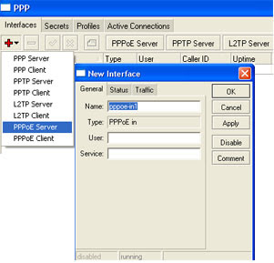
Setting Up Mikrotik PPPoE Server


Tutorial Mikrotik VPN : EoIP
When the bridging function of the router is enabled, all Ethernet level traffic (all Ethernet protocols) will be bridged just as if there where a physical Ethernet interface and cable between the two routers (with bridging enabled). This protocol makes multiple network schemes possible.
Network setups with EoIP interfaces:
* Possibility to bridge LANs over the internet
* Possibility to bridge LANs over encrypted tunnels
* Possibility to bridge LANs over 802.11b 'ad-hoc' wireless networks
An EoIP interface should be configured on two routers that have the possibility for an IP level connection. The EoIP tunnel may run over an IPIP tunnel, a PPTP 128bit encrypted tunnel, a PPPoE connection, or andy connection that transports IP. Specific properties:
* Each EoIP tunnel interface can connect with one remote router which has a corresponding interface configured with the same 'Tunnel ID'.
* The EoIP interface appears as an Ethernet interface under the interface list.
* This interface support all features of and Ethernet interface. IP addresses and other tunnels may be run over the interface.
* The EoIP protocol encapsulates Ethernet frames in GRE (IP protocol number 47) packets (just like PPTP) and sends them to the remote side of the EoIP tunnel.
* Maximal count of EoIP tunnels is 65536
This is how to set up EoIP to bridge two (or more) Mikrotik routers for central PPPoE authentication
Using 2 routers called R1 and R2 that have an IP connection between them and R2 has 2ethernet ports, i.e. you can ping R2 form R1 and R1 form R2 where the R1 facing eth port is called eth1 and its other port is called the2.
1. Create a new EoIP tunnel on R1.
2. Create a new EoIP tunnel on R2, where the tunnel ID is the same as the one on R1 but the MAC address are different.
3. Create a new bridge on R1 and R2
4. Add a PPoE server to the Bridge on R1
5. On R2 and add eth2 and the EoIP tunnel to the Bridge.
6. Put an IP address onto eth2 (any address seem to work, but it maybe better to use a different subnet for routing purposes).
Now you should be able to establish a PPPoE connection form a PC plugged into the eth2 port on router R2, this PPPoE connection will terminate on router R1.
This is not the most efficient method of using the available bandwidth on a network, but is perhaps easier that having a PPPoE A/C on every Mikrotik router and using RADIUS as you can just have PPP secrets setup on one router.
Friday, November 28, 2008
How to Block Websites with Mikrotik proxy
First, Configure Proxy.
/ip proxy
enabled: yes
src-address: 0.0.0.0
port: 8080
parent-proxy: 0.0.0.0:0
cache-drive: system
cache-administrator: "ASHISH PATEL"
max-disk-cache-size: none
max-ram-cache-size: none
cache-only-on-disk: no
maximal-client-connections: 1000
maximal-server-connections: 1000
max-object-size: 512KiB
max-fresh-time: 3d
Now, Make it Transparent
/ip firewall nat
chain=dstnat protocol=tcp dst-port=80
action=redirect to-ports=8080
Make sure that your proxy is NOT a Open Proxy
/ip firewall filter
chain=input in=interface= src-address=0.0.0.0/0
protocol=tcp dst-port=8080 action=drop
Now for Blocking Websites
/ip proxy access
dst-host=www.aaa07.com action=deny
it will block website http://www.aaa07.com, we can always block the same for different networks by giving src-address. it will block for particular source address.
we can also stop downloading files like .mp3, .mp4.....,etc
/ip proxy access
path=*.mp3 action=deny
path=*.mp4 action=deny
try with this also
/ip proxy access
dst-host=:mail action=deny
this will block all the websites contain word "mail" in url.
Example: it will block www.hotmail.com, mail.yahoo.com,.....
Wireless Hotspot Server topology Mikrotik
authentication of clients using local client database, or RADIUS serveraccounting using local database, or RADIUS server
Walled-garden system (accessing some web pages without authorization)
Quick Setup Guide
The most noticeable difference in user experience setting up HotSpot system in version 2.9 from the previous RouterOS versions is that it has become in order of magnitude easier to set up a correctly working HotSpot system.
Given a router with two interfaces: Local (where HotSpot clients are connected to) and Public, which is connected to the Internet. To set up HotSpot on the Local interface:
first, a valid IP config is required on both interfaces. This can be done with /setup command. In this example we will assume the configuration with DHCP server on the Local interface
valid DNS configuration must be set up in the /ip dns submenu
To put HotSpot on the Local interface, using the same IP address pool as DHCP server uses for that interface: /ip hotspot add interface=local address-pool=dhcp-pool-1
and finally, add at least one HotSpot user: /ip hotspot user add name=admin
These simple steps should be sufficient to enable HotSpot system
Please find many HotSpot How-to's, which will answer most of your questions about configuring a HotSpot gateway, at the end of this manual. It is still recommended that you read and understand all the Description section below before deploying a HotSpot system.for complete configuration please visit:http://www.mikrotik.com/testdocs/ros/2.9/ip/hotspot.php
Local Users via Radius Authentication Server

For the purposes of this manual we use Debian GNU/Linux system and FreeRADIUS RADIUS server. Both these products are free software.
*** Mikrotik Router Configuration
Configure the router with proper RADIUS server connection parameters.
[admin@Mikrotik] radius> add service=login address=1.1.1.1 secret="xxx" disabled=no
[admin@Mikrotik] radius> print detail
Flags: X -disabled
0 service=login called-id="" domain="" address=1.1.1.1 secret="xxx"
authentication-port=1812 accounting-port=1813 timeout=300ms accounting-backup=no
[admin@Mikrotik] radius>
Enable local user authorization service to use RADIUS server
[admin@Mikrotik] user aaa> set use-radius=yes
[admin@Mikrotik] user aaa> print
use-radius: yes
accounting: yes
interim-update: 0s
default-group: read
[admin@Mikrotik] user aaa>
*** FreeRADIUS server installtion and Configuration
Install FreeRADIUS server package
root@wildcat:/etc# apt-get install freeradius
Reading Package Lists... Done
Building Dependency Tree... Done
Suggested packegaes:
freeradius-Idap freeradius-mysql freeradius-krb5 freeradius-iodbc
The following NEW packages will be installed:
freeradius
0 upgraded, 1 newly installed, 0 to remove and 269 not upgraded.
Neet to get 0B/1788kB of archives.
After unpacking 4362kB of additional disk space will be used.
Selecting previously deselected package freeradius.
(Reading database ... 60006 files and directories currently installed.)
Unpacking freeradius (from .../freeradius_0.9.3-1_i386.deb) ...
Setting up freeradius (0.9.3-1) ...
Group freerad does already exist as a system group. Exiting...
freerad: freerad shadow
Restarting FreeRADIUS daemon: Stopping FreeRADIUS daemon:
freeRADIUS.
Starting FreeRADIUS daemon: Tue Sep 14 10:50:30 2--8 : infor:
Starting
- Reading configuration files...
freeradius.
root@wildcat:/etc#
Open the files /etc/freeradius/clients.conf and add the following record:
client 1.1.1.3 {
secret = xxx
shortname = xxx
}
This record represents reachable MT router's address (src-address of packets coming form MT router).
Open the file /etc/freeradius/users and add the following line:
ex User-password=="ex"
This adds user named ex which will belong to the default group specified under /user aaa submenu.
To add a user which belongs to the group other then default, you need to supply Group attribute to the router.
Open /etc/freeradius/users file once more and add second user named ex2 which will be the member of group full.
ex2 User-password =="ex2"
Group = "full"
Do not forget to update FreeRADIUS dictionary with additional attributes! Open /etc/freeradius/dictionary file and add the following:
VENDOR Mikrotik 14988
ATTRIBUTE Recv-limit 1 integer Mikrotik
ATTRIBUTE Xmit-Limit 2 integer Mikrotik
ATTRIBUTE Group 3 string Mikrotik
ATTRIBUTE Wireless-Forward 4 integer Mikrotik
ATTRIBUTE Wireless-Skip-Dot1x 5 integer Mikrotik
ATTRIBUTE Wireless-Enc-Algo 6 integer Mikrotik
ATTRIBUTE Wireless-Enc-Key 7 string Mikrotik
ATTRIBUTE Rate-Limit 8 string Mikrotik
Restart FreeRADIUS server.
root@wildcat:/etc# /etc/init.d/freeradius restart
Restring FreeRADIUS daemon: Stopping FreeRADIUS daemon:
freeradius
Starting FreeRADIUS daemon: Tue Sep 14 12:02:05 2008 : info:
Starting
- reading configuration files ...
freeradius.
root@wildcat:/etc#
===================
Configuration testing
To test the configuartion log on to your router as whether ex or ex2 user. Note, that user ex has only read permissions while on the contraty user ex2 has full permission, exempli gratia he can create new users.
Mikrotik OS To Bandwidth Management
A. Install OS Mikrotik
1. Prepare your PC, at least Pentium II, also a father of RAM 64, HD 500M Flash memory or a packet of 64
2. In the server /PC must exist for at least 2 Ethernet, 1 to the outside and 1 more to the local Network will manage the Bandwidth
3. Source Burn CD Mikrotik OS input to the CD-ROM
4. Boot from the CD-ROM
5. Follow the instructions, use the next-next and the default
6. Install the main package, more package with all the bestt way mark
7. After all the package marked for install press the "I"
B. Setting Basic Mikrotik
1. log in as the default admin password it is filled directly enter
2. After the entrace to the command promt type:
[admin@BaseStation]>ip address add address=222.124.21.26/29 interface=ether1
3. Replace with your ip address and the interface will be used for temporary remote
4. Make ping to Mikrotik Server from other computer
5. After connecting procced to the next step, but not repeat steps 2
C. Advanced Settings
1. Mikrotik ip access through a browser, the page will appear and welcome sign in
2. Click the Download link to download the WinBox it's used for remote Mikrotika GUI
3. Run WinBox, Log in as admin password blank
4. Go to the top of the menu (interface), and the interface's not there by clicking the +
5. Add also the interface "bridge" to enable Mikrotik as a bridge
D. Setting Bandwidth Limiter
1. Click on the menu ip> firewall>mangle
Create a rule (click the + red) with the following parameters: On the General tab: Chanin=forward, src.add=192.168.0.2 (or ip i want the limit) in the action tab: Action=marking connection, New connection mark=ropix-con ( or the name of the mark, we make connection) Click Apply and Ok
Create a rule with the following parameters: On the General Tab: Chain=forward, Connection mark=ropix-com (select from the dropdown menu) At the tab Action: Action=mark packet, New packet Mark=ropix (or packet marking, we create) Click Apply and Ok.
2. Queues Click menu> Queues Tree
Create a rule (Click the + red) with the following parameters: on the General Tab: Name=ropix-downstrem (eg), Parent=ether2 (the interface is out of my way), Paket Mark=ropix (select for the dropdown, as we made on the mangle). Queue Type= Default, Priority=8, Limit At=8k (for a minimum bandwidth) Max Limit=64k (limit for setting the bandwidth) Click Apply and Ok.
Create a rule with the follwing parameters: on the General Tab: Name=ropix-Upstrem (eg) Parent=ether1 (is my way into the interface), Mark Packet Mark=ropix (select form the dropdown, as we made on the mangle), Queue Type=Default, Priority=8, Limit At=8k (for a minumum bandwidth upstrem) Max Limit=64k (for setting the bandwidth) Click apply and Ok.
3. Try browsing and downloading form IP, we limit was Rate in Queues rule was to be manage counter, i have not check more steps before
4. Green icon indicates the lack of the bandwidth restrictions (Normal), changed the yellow icon means getting close to limite bandwidth, and red means full.